
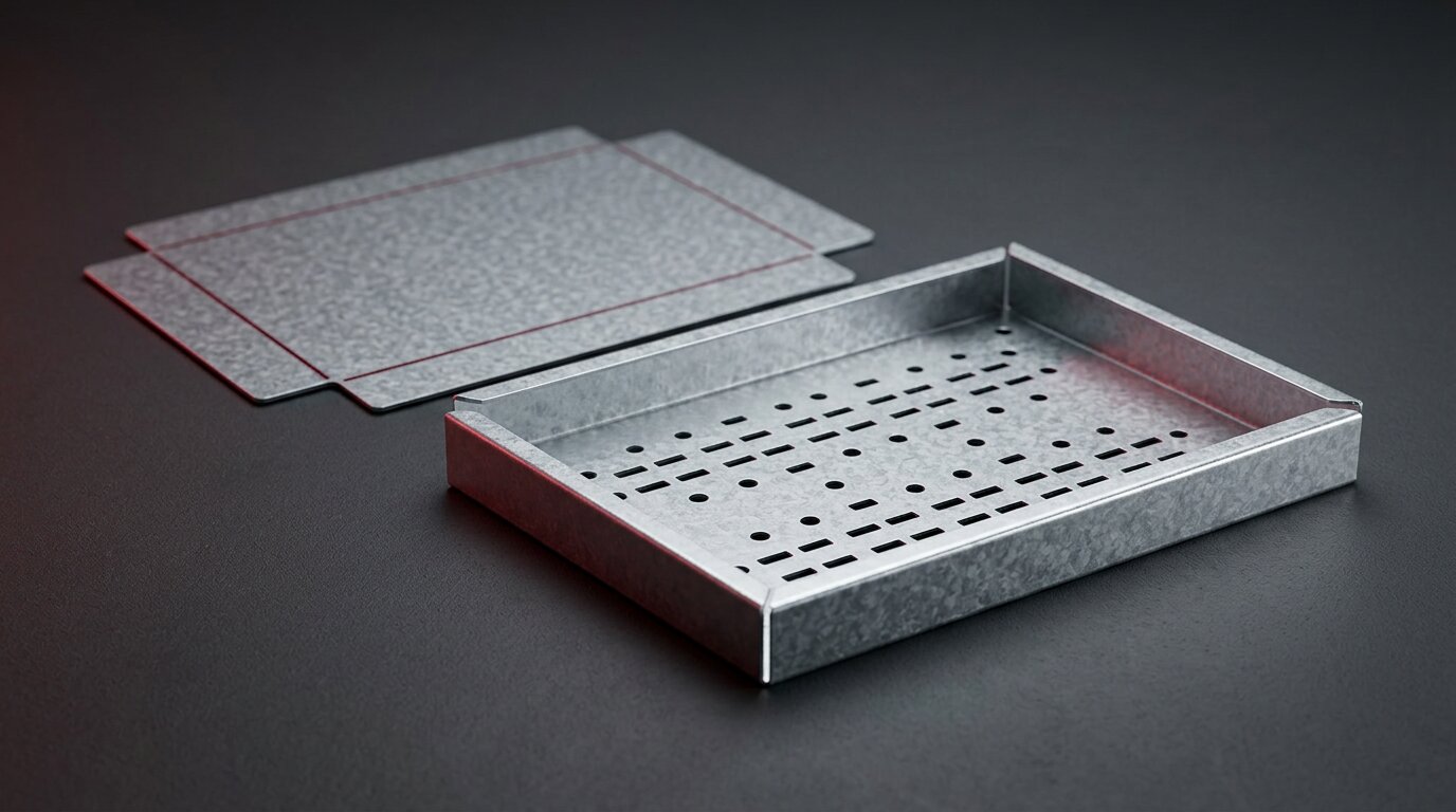
Most fabrication delays do not start on the shop floor. They start earlier, in the gap between a finished CAD model and the information the floor actually needs to cut, fold and assemble a part. A model can be geometrically correct and still create work downstream if the bend allowance does not match the press brake, the DXF carries stray geometry or nobody is sure which revision is current.
This article walks through the sheet metal workflow from model to manufacture, with a focus on the habits that make handover predictable. None of it requires new software on day one. Most of it comes down to agreeing on a few rules, building them into templates and applying them every time a part is released.
Where delays start
When we review sheet metal workflows with fabricators, the same four sources of delay come up again and again:
- Unclear drawings. Missing bend notes, dimensions taken from the wrong face, or a title block that does not say which material and thickness the part is made from. Each of these turns into a phone call or a guess.
- Flat pattern and DXF errors. A flat blank that is a millimetre or two out because the bend calculation in CAD does not match the tooling, or a DXF with bend lines, text and construction geometry all on one layer, so the laser or punch programmer has to clean it up by hand.
- Repetitive manual CAD work. Typing the same part number, material and finish into the model, the drawing and the BOM. Exporting DXFs one at a time. Every manual step is time spent and a chance for the values to drift apart.
- Changes that do not reach the floor. A hole moves or a flange gets longer, the model is updated, but the drawing, the DXF or the cut list on the floor is still the old one.
None of these is a modelling skill problem. They are process problems, and they respond well to standards.
DfM: build the model the way the shop makes it
Design for manufacture (DfM) in sheet metal means the model reflects how the part will really be produced: the material the shop stocks, the tooling on the press brake and the bend method the shop trusts. If the model agrees with the shop, the flat pattern agrees with the folded part.
In SOLIDWORKS, that starts with where the sheet metal parameters live:
- Set thickness, bend radius and K-factor in the sheet metal feature or a gauge table, not as one-off values typed into each part. A gauge table keeps every 1.5 mm galvanised part on the same radius and K-factor, and it is one place to update when tooling changes.
- Agree template rules with the press brake operator. Minimum flange length, standard inside radii for each thickness, relief size and the minimum distance from a hole to a bend line are worth writing down together. The operator knows what the tooling can do; the template makes sure the designer applies it.
- Use one bend method, set from test bends. K-factor, bend allowance and bend deduction can all describe the same fold, but mixing them across parts is where errors creep in. Fold a few test pieces for each material and thickness, measure them and set the values from the results. Then use that method everywhere.
For quick checks away from the CAD seat, our free sheet metal bend calculator runs in the browser with no login required. It is useful for confirming a value on the floor or sanity-checking a gauge table entry.
Make the handover consistent
Once the model follows your DfM rules, the next job is getting the same, complete set of information to the floor every time. Consistency matters more than any single format choice, because the people receiving the files learn what to expect and notice when something is missing.
Export the DXF from the flat pattern, not from a drawing view that someone has re-dimensioned. Put bend lines on their own layer so the programmer can switch them off or convert them to etch marks, and keep outer profile, inner cut-outs and bend lines separate. Write the layer mapping down once and use it in every export. Before sending, open the DXF and check it: closed profiles, no duplicate lines, no stray text or dimensions, and the correct scale.
Name files so they carry the essentials. A pattern such as OTD-DEMO-001_Galv_1.5mm.DXF tells anyone at a glance which part it is, what material it is cut from and how thick it is, before they open it.
| Item | What it includes |
|---|---|
| PDF drawing | Current revision, a flat pattern view with bend notes, and a title block filled from the part properties |
| DXF | Flat pattern only, with bend lines on their own layer |
| BOM / cut list | Generated from the model, not retyped |
| Change note | What changed and where, so nobody has to compare revisions by eye |
If every release contains these four items, the floor can tell straight away when something is missing, and the question becomes "where is the DXF?" rather than "is this the right DXF?".
Automate the repeatable parts
Enter it once, let it flow
Much of the manual effort in sheet metal drafting is re-entering information that already exists in the model. The aim of automation in a DfM workflow is simple: enter each value once and let it flow to everywhere it is needed.
- Custom properties fill the title block. Part number, description, material, thickness and finish live in the part file, and the drawing template reads them. Change the property and the drawing updates.
- The cut list feeds the BOM. SOLIDWORKS already knows the flat blank size, thickness and bend count of each sheet metal body. Let the cut list properties populate the BOM instead of copying them by hand.
- Configurations or design tables for part families. When the same bracket or tray comes in several lengths or hole patterns, drive the variants from one model rather than maintaining a folder of near-copies.
One caution: make the process consistent before you automate it. Automating an inconsistent process just produces inconsistent output faster. Agree the templates, properties and file naming first, then automate the steps that follow those rules.
For the batch jobs that remain, we are developing the OpenTech Drafting Assistant, currently in early access. It is a SOLIDWORKS add-in for batch custom properties, sheet format replacement, DXF and STEP export, search-and-replace across drawing notes and running macros over many files at once.
Keep changes connected
Revision control tends to break quietly. The warning signs are familiar: several versions of the same part in different folders, drawings where the revision status is unclear, and the floor regularly asking "is this the latest?". Each of those questions costs time, and occasionally a wrong part gets made.
A few practical measures go a long way:
- Use revision tables and revision clouds on drawings so the change is visible on the sheet, not just in someone's memory.
- Share eDrawings for review. Customers, supervisors and operators can view, measure and mark up a part without a CAD licence, which keeps feedback tied to the actual model.
- Consider PDM when shared folders stop coping. Once several people are editing the same files, check-in, check-out and controlled release states do the job that folder names and good intentions cannot.
Not every file the shop handles comes from SOLIDWORKS. DraftSight suits 2D work and customer files supplied as native DWG, and it is a practical tool for opening and checking DXFs before they go to the laser or punch.
Start small. One seat, one template and one release standard, applied consistently, will tell you more about what to improve next than a large rollout.
Reviewing the workflow as a whole
Each of the steps above helps on its own, but the real gains come from looking at how they connect: whether the DfM rules in the gauge table match the press brake, whether the drawing template reads the properties the model actually carries, whether the DXF export follows the layer map and whether a change in the model reliably reaches the floor. Reviewing the workflow end to end, from CAD seat to cut part, shows where the handovers break down and which fix will make the most practical difference for your team.
Worked example: demo part, not client work
A simple enclosure tray shows how these values fit together:
- Material: 1.5 mm galvanised steel
- Inside bend radius: R1.5, K-factor 0.44, both set in the sheet metal feature
- Two 50 mm flanges and 2 bends
- Flat blank: 320 × 314.79 mm
- 14 cut-outs
The flat blank size and bend count are the values reported by the SOLIDWORKS cut list. They flow into the BOM without being retyped, and the material and thickness carry through to the file name OTD-DEMO-001_Galv_1.5mm.DXF.
If your team spends too much time preparing drawings, repeating CAD tasks or answering "is this the latest?" questions before fabrication, book a workflow review with OpenTech Designs. We'll look at how work moves from your CAD seat to the floor and where the practical improvements are.
Book a workflow review